
Marcos
Wednesday, December 10, 2014
Electronics Projects
TCC Liceu
Development
Start: 09/2014.
End: 11/2014.
Project description
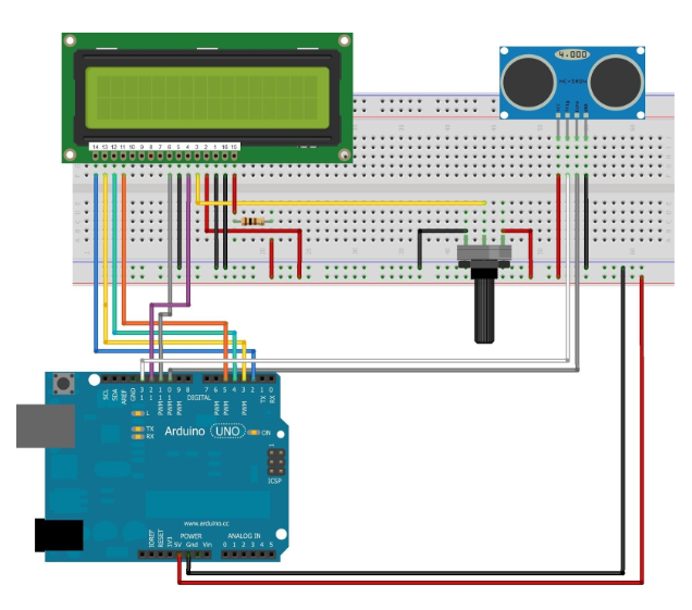
This work aims at the implementation of electronic concepts for the creation of a project that assists the parking of an automotive vehicle. The circuit used will detect obstacles through the use of an ultrasonic sensor, which will emit sound waves that will be reflected by the object. Their return time will determine the distance between the vehicle and the obstacle. If the distance is short, a sound alert will warn the driver, thus avoiding possible accidents and damage to the vehicle.
Screenshot


Tools
- Arduino
- Buzzer
- Ultrasonic sensor SRF04
- LCD Display
LED Bargraph
Development
Start: -/2013.
End: -/2013.
Project description
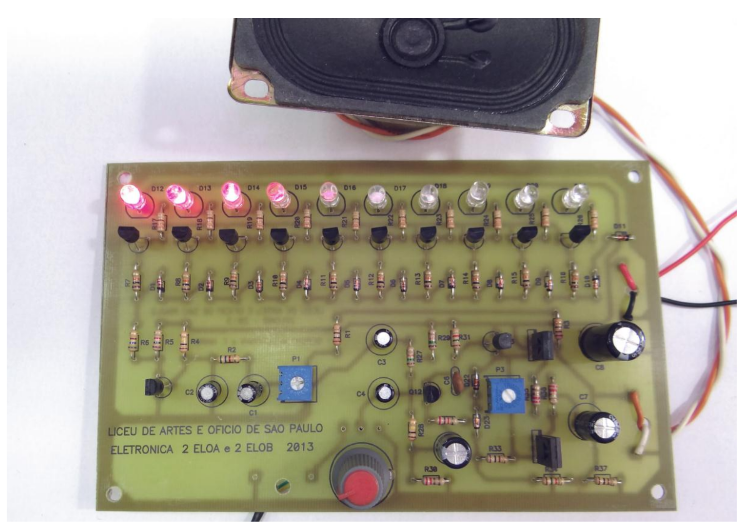
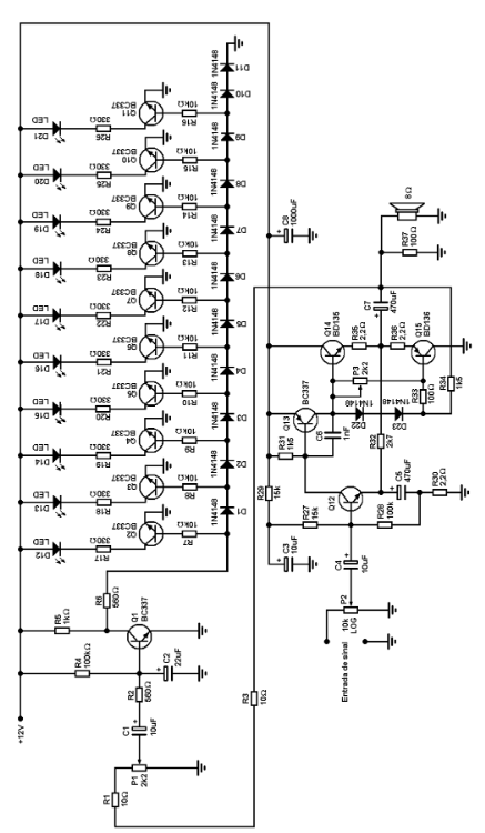
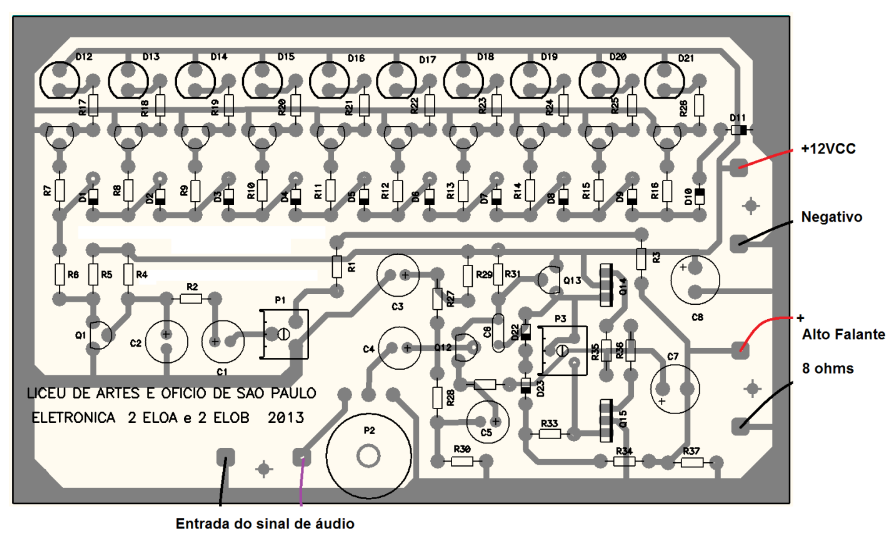
An LED bargraph is a visual display that responds to audio frequencies. It consists of a series of LEDs arranged in a linear configuration. The incoming audio signal from a device, such as a cell phone, is filtered into different frequency ranges using transistors. Each LED is associated with a specific frequency range, and when the audio signal falls within that range, the corresponding LED lights up. The LED signals are amplified and transmitted to a speaker, allowing the LEDs to light up in synchronization with the music being played from the connected device. This creates an engaging visual representation of the audio, where the LEDs illuminate and change intensity in response to the music’s frequencies.
Screenshot
Tools
- Speaker
- LEDs
- Capacitors
- Homemade board
- Transistors
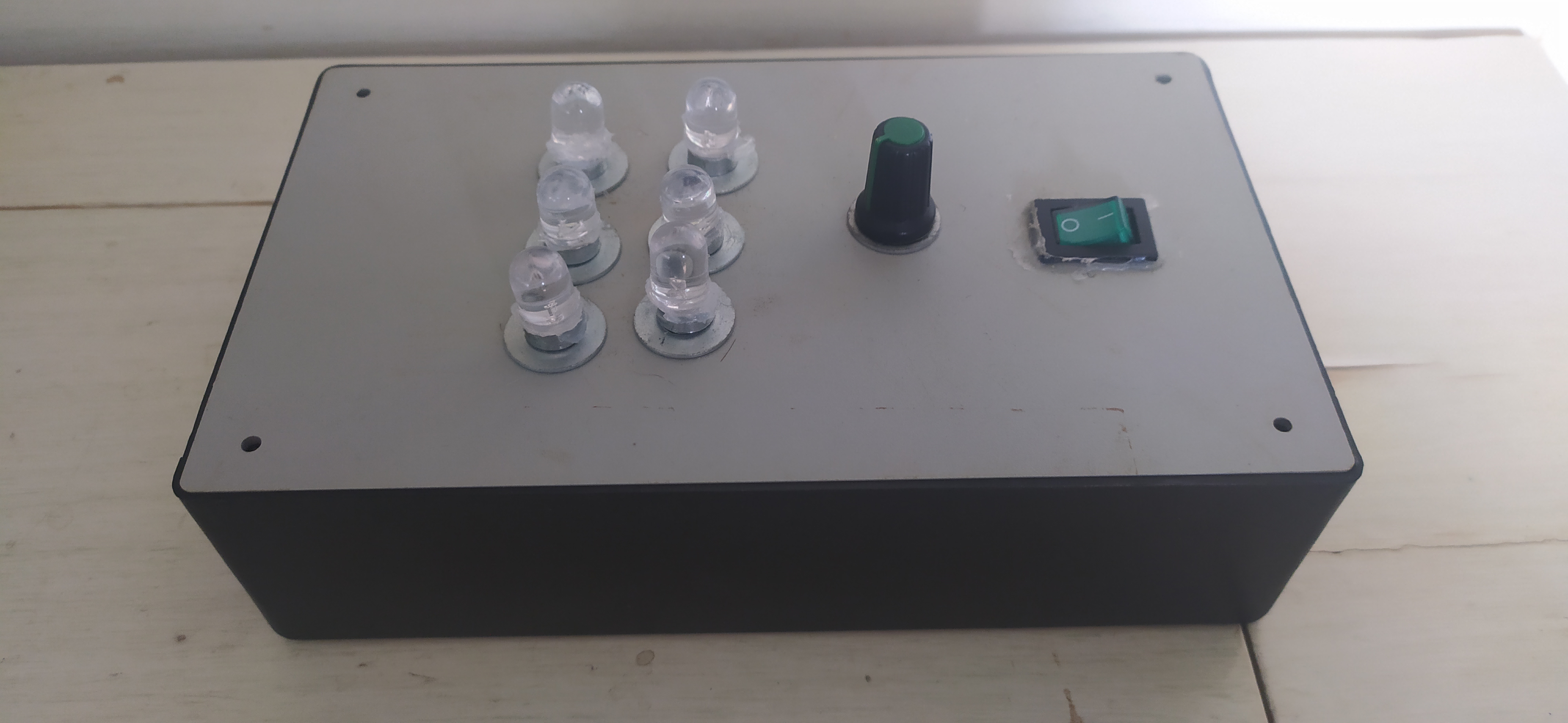
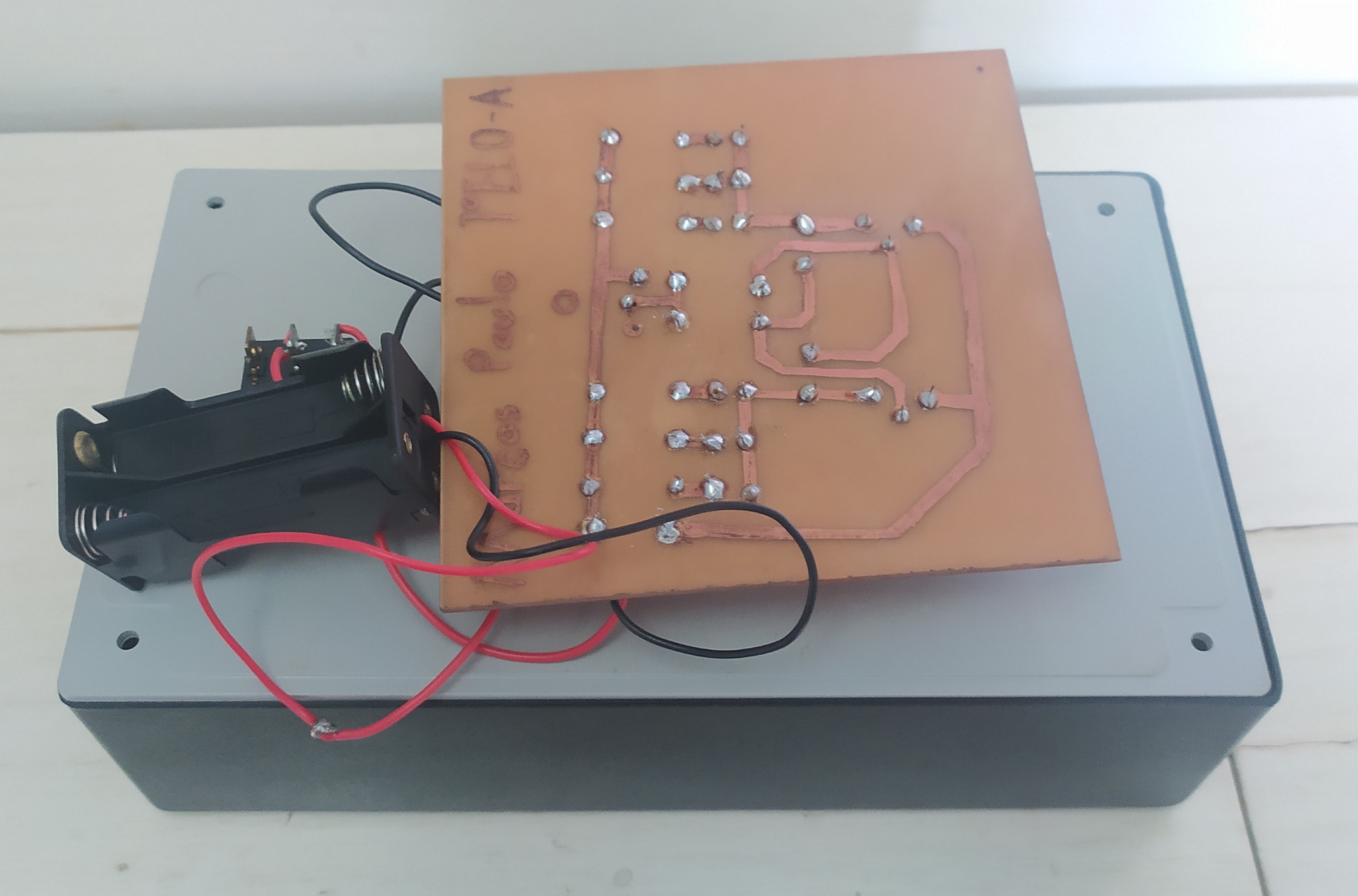
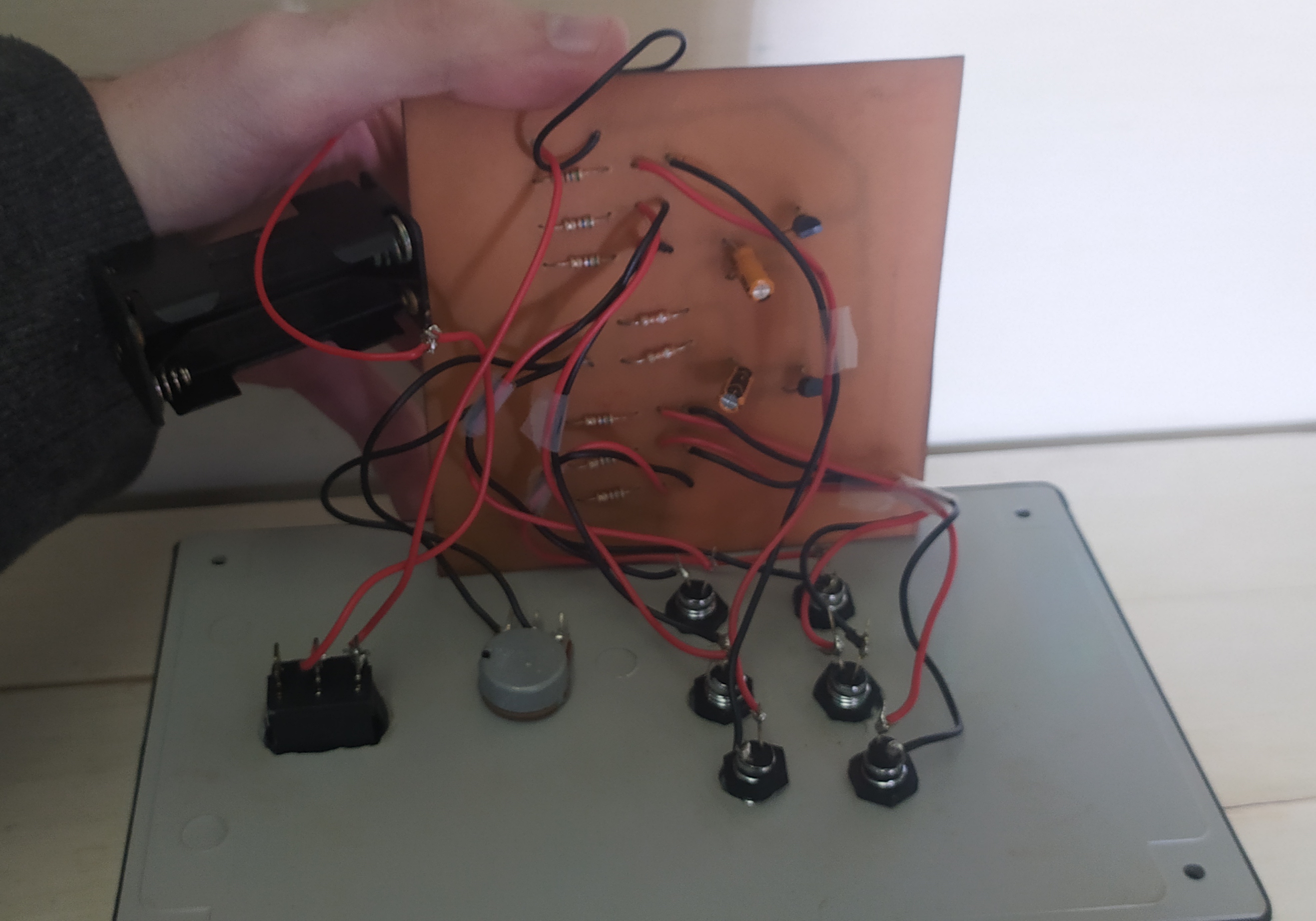
Analogic Blinking LEDs
Development
Start: -/2012.
End: -/2012.
Project description
An analog blink circuit, also known as an astable multivibrator, is an electronic circuit that generates a continuous blinking or oscillating output signal. It typically consists of two transistors, capacitors, resistors, and a power supply.
Here’s how it works:
-
Initial State: The circuit begins in an unstable state where one transistor is in the “ON” state (conducting) and the other is in the “OFF” state (non-conducting).
-
Capacitor Charging: The capacitor connected to the “ON” transistor starts to charge through a resistor. As the voltage across the capacitor increases, it eventually reaches a threshold level.
-
Switching Transistors: Once the threshold voltage is reached, it triggers a switch, causing the “ON” transistor to turn off and the “OFF” transistor to turn on.
-
Capacitor Discharging: The capacitor connected to the “OFF” transistor starts to discharge through another resistor. As the voltage across the capacitor decreases, it eventually drops below a threshold level.
-
Switching Transistors Again: Once the threshold voltage is reached, it triggers another switch, causing the “OFF” transistor to turn off and the “ON” transistor to turn on again.
-
Repeat Cycle: The process repeats, with the transistors switching back and forth in an oscillating manner. This results in a continuous blinking or oscillating output signal.
By adjusting the values of the resistors and capacitors in the circuit, you can control the frequency and duty cycle of the blinking signal. Although simple the analog blink circuit is very used in applications such as blinking LEDs, timers, and oscillators.
Screenshot
Tools
- LEDs
- Homemade board